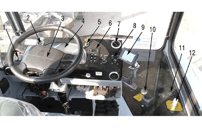
Interior Cab Devices
1. Rockerswitcharea
2. Transmission oil temperature gauge
3. Steering wheel
4. Combination instrument
5. Engine speed per hour
6. Gearbox shifter
7. Air-conditioning air outlet
8. Air-conditioning control panel
9. LNG liquidometer
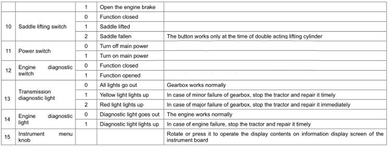
10. Parking brake handle
11. Electric cigarette lighter
12. Saddle air lock switch
Instrument Board Of Interior Cab Devices
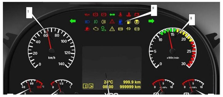
1. Speedometer
2. Water temperature gauge
3. Fuel gauge
4. Small mileage/small mileage fuel consumption reset button
5. Information display screen
6. Barometer 1
7. Barometer 2
8. Engine speed meter
9. Signal light
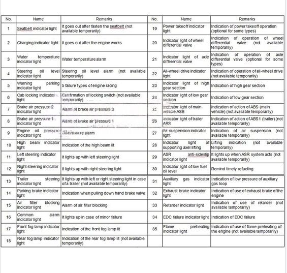
Summary sheet of symbols of signal lights
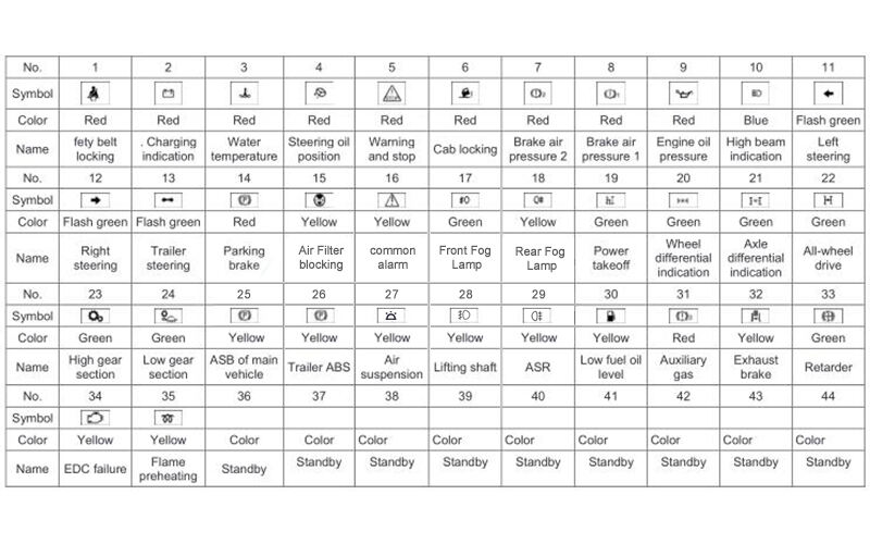
Function specifications of signal light
Signal switch and function (excluding rocker switch):
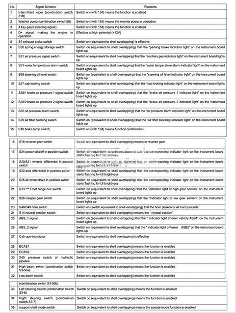
Lorem ipsum dolor sit amet, consectetur adipiscing elit. Ut elit tellus, luctus nec ullamcorper mattis, pulvinar dapibus leo.
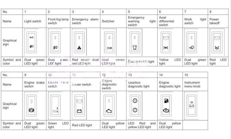
Graphic symbols of rocker switches
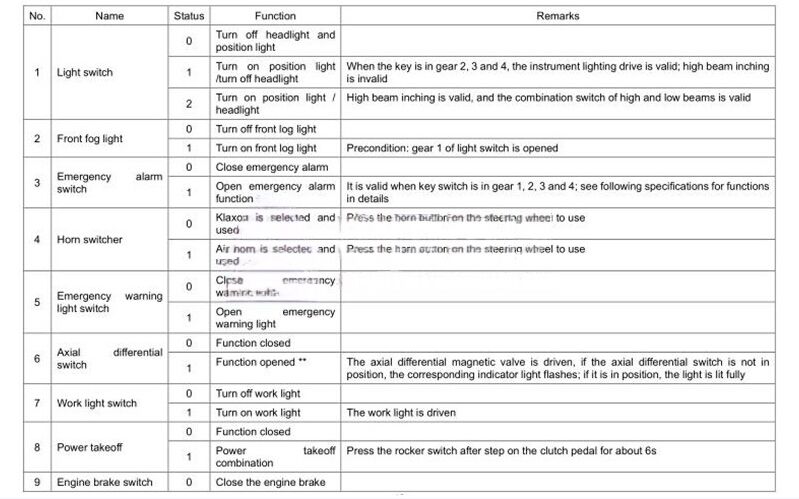
Function specifications of rocker switches (indicator lights included. Unless otherwise stated, the key start switch in gear 1 is invalid )
Description:
** when the axis difference switch is pressed, the axis difference signal light on the instrument flashes, if the axis difference lock signal switch has a feedback signal within 5s, the axis difference signal light is lit; in case of no feedback signal, check the drive output of axis difference magnetic valve, if the drive output is normal, the axis difference signal light is lit. The lamp may have fogged with a big humidity change and fog disappears if the light is on.
Power Switch Of Interior Cab Devices
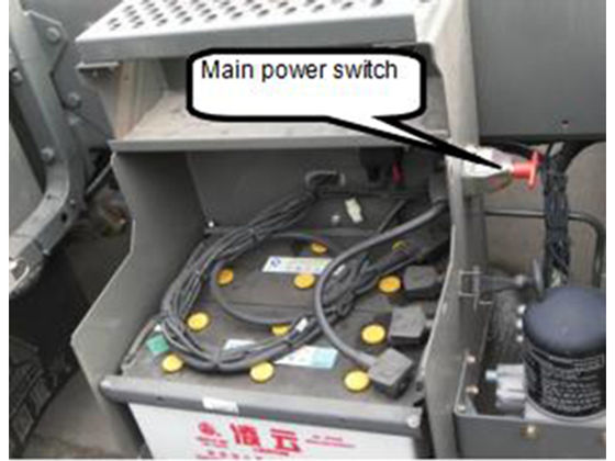
1. Main power switch
The main power switch is outside the battery compartment (getting-on ladder) of the left longitudinal beam of the frame.
Note: when the tractor stops for a long time, turn off the main power switch to avoid an accident.
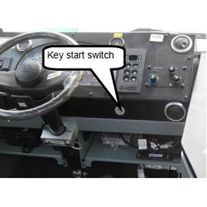
2. Key start switch
The key start switch is arranged on the right of the instrument desk.
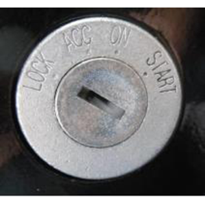
|
Turning position |
Usage |
Remarks |
|
1 (LOCK) |
Outage of whole tractor |
The key can be pulled out now |
|
2(ACC) |
Connect the electric equipment when the tractor stops |
|
|
3 (ON) |
Driving position |
|
|
4 (START) |
Start the engine |
Automatic reset to gear 3 |
Combination Switch Of Interior Cab Devices
1. Operation of turn light:
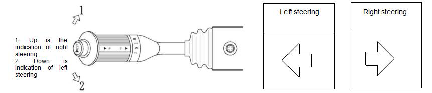
Note: when the turn light works, the steering indicator light on the instrument board flashes meanwhile. When the turn light bulb is damaged (total power of the bulb is less than 21W), the flashing frequency is increased (work in frequency multiplication), the steering indicator light also gives the indication of frequency multiplication, and meanwhile, the information screen displays the failure.
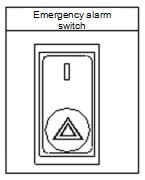
2. Emergency alarm
Turn on the main power switch, press the emergency alarm switch (as shown in Figure 2.6), and all turn lights and steering indicator
lights flash.
3. Headlight operation:
- The combination switch handle is in neutral position, the key switch is in gear 3, the light switch (as shown in Figure 2.7) is in gear 2, the low and high beams of the headlight (as shown in Figure 2.8) are lit. Now, the combination switch handle is pulled up to 4 degrees, the high and low beams are completely lit and can be as instantaneous light of night overtaking or passing; the handle is pulled up continuously to 10 degrees, the changing light is available: the high beam becomes the low beam or the low beam becomes the high beam. Let go of the handle.
- At the time of day overtaking or passing, the handle is pulled up to 4 degrees, the high beam is lit, and let it go and it is automatically reset.
4. Wiper operation
0—Closed position J– Wiper intermittent gear
I– Wiper slow gear II– Wiper fast gear
Press — windshield washing system
5. Horn button
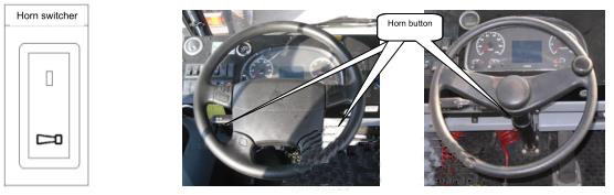
The tractor is equipped with the klaxon and electrically controlled air horn and they are switched by a horn switcher.
The horn button is on the steering wheel. In case of use of electrically controlled air horn, press the horn switch (rocker switch)
and horn button on the steering wheel successively.
Operation of fog lamp and interior lighting
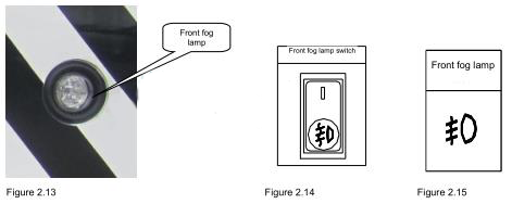
1. Operation of front fog lamp
The light switch is in gear 1;
Press the front fog lamp switch (as shown in Figure 2.14) and the front fog lamp (as shown in Figure 2.13) is turned on. Meanwhile, the front fog lamp indicator
light on the instrument board is lit (as shown in Figure 2.15).
Note: the front fog lamp can be operated only when the light switch is turned on.
2. Interior lighting
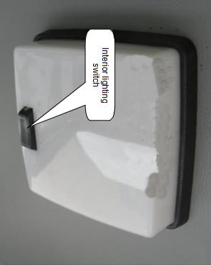
(1) Turn on the interior lighting switch
(2) Press the left or right side of the switch on the interior light, and the interior lighting system will be lit always.
(3) Turn off the interior lighting switch
Put the switch on the interior light in neutral position.
Seat Of Interior Cab Devices
1. Air suspension seat
The optimization, matching and combination of air spring and hydraulic damping are made
for the seat.
The suspension seat consists of the air spring, leveling valve, hydraulic damper, metal
member, breakdown prevention elastic parts, etc.
The seat height can be adjusted according to the people weight and road situation, which
greatly improves the comfort of the seat.
Technical parameters
Seat width: 500mm
Seat height: 865mm (maximum)
Height adjustment: 7 gears within the range of 0 – 65mm
Forward and backward adjustment: 5 gears within the range of 0 – ±75mm
Backrest angle adjustment: 0° – 41.4°(backward from the plumb line) and 0° – 60° (forward
from the plumb line)
Use method
- 1) Adjustment of backrest elevation pull the handle 1 up to turn the backrest to the required degree, loosen the handle, and lock the backseat position.
- 2) Adjustment of rear-end height
Softly pull the handle 2 up, meanwhile, apply appropriate force upward (downward) to the rear end of the seat to make the rear end go down (up) to required
position, and loosen the handle. - 3) Adjustment of rear-end height
Softly pull the handle 3 up, meanwhile, apply appropriate force downward (upward) to the rear end of the seat to make the rear end go down (up) to required
position, and loosen the handle. - 4) Adjustment of anteroposterior position
Pull the handle 4 up to move the seat forward and backward to the required position, and loosen the handle. - 5) Height locking handle
The seat will be in the lowest position when the airbag or other damping component is damaged or invalid; for the convenience of driving, the seat can be lifted to
appropriate height, the handle 5 is turned from horizontal position to the vertical position (bottom seat plane as datum plane) and locked to keep the seat at fixed
design height.
Note: in the case of an air spring seat, pay attention to the height locking handle on the front lower part of the seat, the horizontal position is inflating position
and vertical position is lock position.
Transmission shifting Of Interior Cab Devices
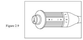
1.Push-button gear selector (automatic gearbox is as shown in Figure 2.18)
- (1) Forward gear s switch (press Button D)
When speed it up, the gearbox will automatically rise from the available lowest gear to the top gear in
order;
When slow it down, the gearbox will automatically change gears down; - (2) Reverse gear switch (press Button R)
When selecting the reverse gear, the tractor must stop completely, the engine returns to the idle state, switch to the
reverse gear through neutral gear, and now the shifter displays “R”; - (3) Neutral gear switch (press Button N)
In the neutral gear state, the selector displays “N”. - (4) Gear shift mode switch
According to different road conditions and loads, the economic mode and power mode can be selected;
In power mode, the display screen will display “MODE”. - Economic mode: default operation mode, the fuel consumption is low but the power take-off is relatively
poor;
Power mode: at the time of operation in power mode, more power take-off is available,
but shifting point is relatively delayed and the fuel consumption is increased.
Note: the power mode is recommended only when the tractor seriously lacks of power,
or goes up the slope, or is supercharged. - (5) After selecting gear D, manual upshift or downshift can be realized by pressing the upshift button ↑ or
downshift ↓.
Figure 2.19
31 - (6) Read the oil level of the gearbox by the shifter
Entry mode: press both upshift button ↑ or downshift ↓;
Exit mode: exit the oil level check mode by pressing the neutral gear button N;
Conditions for oil level check:
① The tractor is parked on level road;
② The engine is in idle running state;
③ The gearbox is in neutral gear state;
④ The rotational speed of output shaft is zero;
⑤ Tense the parking brake;
⑥ The oil level of the gearbox is stable;
⑦ The oil temperature of the gearbox is in normal
measurement range of 60-104℃. - Note: see the Allison Operation Manual attached for detailed operation process

2. Shifting handle (mechanical gearbox as shown in Figure 2.20 and 2.21)
The shifting handle of the transmission feels good, simple in operation, and greatly reduces the driver’s labor intensity. It is installed on the cab floor, seldom has
gear off problem, and does not affect the cab turnover.
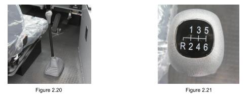
1. Control mechanism
The control mechanism of ZF transmission (S6-120) is mechanical soft-axes control and simple in gear shift. There are six forward gears and one reverse gear.
Two pictures above show the position chart of shifting handle of the shifting mechanism and transmission position (position of guide block of top cover).
Parking Brake Of Interior Cab Devices
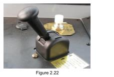
(1) Position in Figure 2.22 is the parking brake position.
(2) Loosen the hand brake, push the handle forward and upward successively in the direction of driver
(you can hear the louder deflated sound)
(3) Parking brake, pull the handle down (you can hear inflation sound)
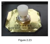
Unlocking control button of traction seat
Using the traction seat can make the tractor go up and down, and this is automatic reset gas-controlled
switch (as shown in Figure 2.23)
Press the traction seat to unlock; the internal mechanism in the traction seat is automatically locked under
the forward impact of traction pin.
Note: please don’t press on driving
Saddle lifting Of Interior Cab Devices
Type of lifting cylinder
There are three types of lifting cylinder for saddle-lifting tractor:
Single-stage double-acting cylinder (lifting height of 405);
Double-stage double-acting cylinder (lifting height of 705);
Double-stage single-acting cylinder (lifting height of 705);
Saddle lifting operation
Saddle lifting operation: switch on the power, the key start switch is in gear 2
(ACC) or 3 (ON), long press “1” face of the rocker switch (Figure 2.23), and the
saddle is lifted;
Saddle lowering operation: switch on the power, the key start switch is in gear 2
(ACC) or 3 (ON), long press “2” face of the rocker switch (Figure 2.23), and the saddle is lowered;
Seatbelt Of Interior Cab Devices
- Fasten the seatbelt
Pull the lock catch for the seatbelt (as shown in Figure 2.26) bypassing the shoulder, put the latch into the buckle
until they are meshed. - Unfasten the seatbelt
Press the red button on the lock catch for the seatbelt in the direction of arrow, pull the latch out, and make the
seatbelt automatically return to original position.
Note: please fasten the seatbelt before driving every time! Check the situation and function of seatbelt
every day. - Seatbelt alarm description
2.3.1. Turn the key switch to the driving position, and if the seatbelt is well fastened, the seatbelt lock signal light
on the instrument board is out; if not, the signal light is always lit and the buzzer does not ring.
2.3.2. After the engine starts, and if the seatbelt is not well fastened, the seatbelt lock signal light is lit, and the
buzzer rings at low frequency and stops ringing after 6s; after the seatbelt is well fastened, the signal light goes
out and meanwhile the buzzer stops ringing.
2.3.3. During the engine operating process, if pull the seatbelt out, the signal light will be lit and the buzzer will ring
at low frequency for 6s.
Other Internal Devices Of Interior Cab Devices
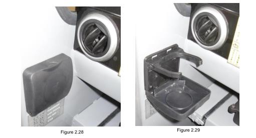
Cup base (as shown in Figure 2.28 and 2.29)
The cup base is in the left side of the cab and close to the instrument desk: pull outward to open the cup base to place the cup, and return to original position if it
is not used
Preparations before driving
- Warning: keep the tractor in good condition, and do not drive with failure!
1. Routine check before driving every time
- Switch on the tractor power
Rotate the red handle (as shown in Figure 3.1) 90 degrees anticlockwise to open the main power switch. - Check the working condition of entire circuitry (self-test of system)
After the key switch is turned on (in ON), that is, KL15 is connected, the bus system carries out the
self-test.
Actions of various devices are as follows hereafter:
- All instruments: the pointer of the instrument rotates to the full scale from mechanical limit within 2 s after power on. Later, the odometer and engine tachometer return to zero position, and the barometer, fuel gauge and water temperature gauge indicate the measured value of current system.
- All indicator lights: all are lit for 1s and then return to actual state.
- LCD: 2s interval, display LOGO of CNHTC and normal travel page successively (display the voltage and engine oil pressure).
- After completion of self-test, if any current axle and wheel differential lock switches and all-wheel drive switch is closed, the differential lock indicator page will be displayed;
- If the differential lock is not closed and the system has a failure, the page displays the error information;
- If both situations above do not occur, while the indicator of other working indicator pages works, the system will jump to the indicator page;
- If three situations above do not occur, the system stays the normal travel page.

2.Check the coolant, fuel oil and engine oil
- (1) Check the coolant
The expansion tank is in the engine maintenance chamber and the coolant can be filled after open this chamber.
Check the level of coolant in the expansion tank (as shown in Figure 3.2), and if the level is too low, the coolant with stipulated specification shall be filled until reaching the stipulated scale mark.
The pressure relief valve can keep the cooling system have a certain pressure to atmosphere to increase the boiling point of the coolant.
The pressure relief valve plays a more important role in the plateau area and cannot be replaced and damaged at will.
When the engine is in the high temperature state, the coolant shall be filled by two steps:
- Step 1: the high pressure is relieved at the feeding mouth;
- Step 2: open the cover and fill it up with coolant when the engine is at idle speed.
- Warning: do not feed the coolant when the engine is in the high temperature state!
- Note: it is strictly prohibited to cut the connection between the storage battery and central computer before the ignition key and other input powers with wakeup function are turned off! Or otherwise, it may damage the electronic control unit, wiring harness and electrical and electronic components of the systems of the tractor in the aspect of hardware, even cause the severe consequence of loss of system data! 3. Check the coolant, fuel oil and engine oil
- (2) Check the fuel oil quantity
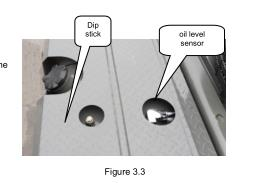
Turn on the key switch, check the fuel oil quantity on the fuel gauge or by taking out the dip stick in the fuel tank (as shown in Figure 3.3).
If finding the indication of fuel gauge is incorrect, please check the fuel gauge and oil level sensor. - (3) Check the engine oil quantity
The tractor is parked on the level road, after the engine cooling, pull out the dipstick (as shown in and the engine oil level shall between the upper and lower scale marks (the oil quantity between upper and lower scale marks is about 3L). If the level is lower than the lower scale mark, the engine oil with stipulated specification shall be filled until reaching the stipulated level and cover the oil filler cap tight.
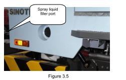
- Warning: please fill the spray liquid with designated brand, or otherwise, the wash line will be blocked
(4) Fill the spray liquid
The spray liquid filler port is on the left pedal of the cab (as shown in Figure 3.5). Uncover the outer cover, pull out, rotate and adjust the filler port as shown in the figure, and fill the spray liquid.
- 5. Check the tire pressure
The tire pressure must be normal during the tire use process.
The wheel and tire size required of the tractor are used.
The tire is aging gradually because of sunniness and environmental factors. The tire (spare tire) shall be replaced once every six years at least after use for six years. - 6. Check the leak of lubricating oil, coolant and gas circuit
- 7. Check the engine intake system
(1) Check the pre-filter
Check whether the pre-filter inlet is blocked with foreign matters to prevent the too high negative pressure of the air intake system; check whether the pre-filter impeller rotates freely, or otherwise, the pre-filter shall be maintained or replaced to prolong the maintenance period of the air intake system.
(2) Check the air filter
Check whether the pipe between the pre-filter outlet and supercharger inlet is damaged, if so, it shall be blocked timely and replaced with new pipe, or otherwise, it will causes serious early wear of the engine.
8. Check whether there is people or obstacles around the tractor before starting and driving
Engine start
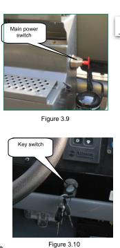
Main power switch (as shown in Figure 3.9)
Main power switch is outside the battery compartment (getting-on ladder) of the left longitudinal beam of the frame.
Key switch (as shown in Figure 3.10)
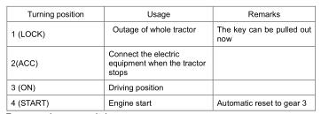
1. Turn on main power switch
Turn the key switch to position 4 (STAT) to start the engine.
Note: during the driving process, do not turn off the key switch, that is, the key switch is in position 3 (ON) in the driving
2. Starting process
Connect up the hand braking. The gear shift lever is put in the neutral position. Turn the key switch to start the engine.
The charging indicator light goes out after the engine starts.
- Note: 1. If it fails the first time the engine starts, the key switch shall be put in gear 2 again to restart.2. Every starting time is not more than 15s and the interval between two starts is not less than 30s. 3. Engine oil pressure after starting
After the engine starts, observe the pressure value of the oil pressure gauge and meanwhile the oil pressure indicator light shall go out.
- Warning: never make the cold engine runs at high speed! If the oil pressure gauge does not work after the engine starts, the engine shall stall immediately and maintain it.
3. Use of the supercharger
- The superchargers of different engines are located at different positions. MC07/MT07 engine supercharger is in middle of the right side of the engine, WD615/WT615 and D10/T10 engine superchargers are installed at upper back of the engine. The supercharger consists of the turbine component and pump pulley component.
- The exhaust gas from the engine blows the turbine to rotate and drive the coaxial pump pulley to rotate at high speed, to deliver the compressed air into the engine intake duct to boost the intake pressure so as to increase the engine power. The speed of rotor in the supercharger is high, and the lubrication of rotor bearing is forced lubrication and the pressure-feed lubrication is provided by the main oil duct of the engine. The engine shuts down and the oil supply stop.
Attention should be paid at the time of operation:
- ①. The engine shall run at idle speed for 3-5 min at the time of start; do not slam on the accelerator; apply the load after the engine oil pressure and temperature are normal (especially start in cold day), or otherwise it easily causes the early wear of the bearing and sealing ring for lack of oil.
- ② At the time of stalling, the engine shall run at idle speed for 3-5 min and can stall after the supercharger speed is reduced. Particularly note that do not slam on the accelerator before stalling, the supercharge will be realize high speed for the engine speed suddenly rises for slam on the accelerator, the engine stalls suddenly now, the engine oil pump stops oil supply, the supercharger rotor still runs at high speed because of inertia, the rotor spindle, bearing and sealing ring will be burnt up for lack of oil.
-
③ The pre-lubrication must be conducted for the supercharger before the engine restarts after a long-term shutdown. The pre-lubrication is realized by disassembling the inlet tube of the supercharger and pouring appropriate clear lubricating oil from oil inlet, or otherwise, the initial start will have early wear for lack of oil.
(III). Stalling of engine
Turn the key switch to LOCK position and the engine stalls. Turn off the main power switch after stalling.
- Note: The engine temperature is high after overloading work, so it stalls after running 3-5 min. When the pressure does not reach the required pressure value, the engine cannot stall normally (this is normal phenomenon), the engine can stall normally after the pressure reaches the required pressure value.
Starting and gear shit
1. Starting
After the engine starts, if the air pressure is low and warning light is lit, do not start. After the charge pressure reaches 0.55MPa and the warning light goes out, loosen the hand brake handle and ready to start. Before the air pressure in the air cylinder (read from the double-pointer barometer) reaches 0.7Mpa, the tractor does not completely reach the state suitable for running; only after that, the brake can reach the required brake performance.
2. Running and gear shift
1. Basic operation
- (1) At the time of starting, gently step on the accelerator.
- (2) The tractor must stop completely from forward gear to reverse gear or in reverse.
- (3) The sliding in neutral gear is strictly prohibited, or otherwise, it seriously damages the gearbox.
- (4) Pay attention to supervision of the temperature of the engine and gearbox at the time of running.
- (5) When the tractor is dragged because of failure, especially it is dragged for a long distance for engine stalling, the transmission shaft shall be disconnected or make the driving wheel off the ground. The gear shift lever is in neutral gear when the tractor with mechanical gearbox is dragged.
- (6) In case of worse road conditions, the tractor runs by adjusting the gearbox to the gear 4 or less.
2. Precautions
- (1) Precautions of the tractor with automatic gearbox
1). Check whether the gear selector displays the neutral gear when the tractor starts, that is, the gear selector displays N; - 2). The idle speed of the engine shall be about 600RPM, and too high or low idle speed may cause that the transmission cannot put into gear;
- 3.) Under any condition, when the tractor with automatic gearbox keeps in the neutral gear, do hold the brake to prevent the accidental movement of the tractor;
- 4). When change the direction and gear, the tractor must stop completely, switch the gear through N gear and the gear selector shall display corresponding gear;
- 5). When carrying out the gear shift operation, if the code of selected gear is flashing, it means that the current operation is suppressed and the gearbox is still in previous gear before this operation;
- 6).If the tractor has the gear locked during the running process, do not stall the tractor right immediately and keep the current gear to drive it to appropriate parking position or repair plant; If stall the tractor now, the tractor may be unable to select the gear when it restarts;
3. Oil saving tips
a. When the tractor starts, gently step on the accelerator and do not slam on it, which can save the fuel oil.
b. At the time of pit stop or stopping at a red light for a long time, shift the gearbox gear to neutral gear, which can help saving the fuel oil.
c. Loosen the accelerator to let the tractor slide before stop or stopping at a red light, avoiding the brake stop, which can save the fuel oil.
d. Do step on the accelerator and do not slam on it during the running process, which can shift the gear faster and save the fuel oil.
e. Guarantee correct oil level of the gearbox, which can improve the gear shift performance and save the fuel oil.
Saving tips:
a. The tractor tries to run at high gear during the running to ensure the engine operating condition in economic speed range.
b. When the tractor accelerates, the “gear skipping” (skip a gear) operation is allowed to make full use of engine power.
c. The tractor shall put into high gear at the time of downhill driving to make full use of engine brake.
d. Pay close attention to road condition, use the neutral gear, and make the tractor run by using the inertial.
e. Do not frequently use the emergency foot braking or suddenly speed up when unnecessary.
4.Assembly and adjustment of clutch control system
- (1) Check and adjust the clearance between the master cylinder push rod and piston.
At the time of assembly, gently screw the pull rod with hands to adjust the length until reaching the piston, and then screw it back for a thread to guarantee the clearance between the push rod and piston of 0.7mm – 1mm, and the tighten the nut. The clearance shall not exceed 1mm, or otherwise, it will reduce the effective stroke of master cylinder, affecting the clutch release result. - (2) Check and adjust the free stroke of push rod of power cylinder
The clutch release bearing shall have a free stroke of 2mm – 3mm to prevent the bearing from long-term press work and early damage, so the push rod of the power cylinder shall have a free stroke of 6mm – 8mm. At the time of assembly and adjustment, the return spring is not installed, the piston and push rod are pushed by the preloaded spring in the power cylinder to reach the clutch release lever, now adjust the limit bolt to keep the clearance between the bolt top and holder of 1mm, tighten the jam nut, and then install the return spring. - (3) Exhaust the air in the hydraulic system.
There is air in the hydraulic system of the clutch, the effective stroke of piston push rod of power cylinder will be reduced, so the clutch release is not thorough and the gear engagement is difficult. At the time of assembly or disassembly of oil pipe, loosen the vent valve of power cylinder first, feed the brake liquid with required brand in the oil storage tank, feed it as step on the clutch pedal until the liquid overflows from vent valve, and then tighten the vent valve. To fast and thoroughly exhaust the air in the system, the sectioning exhaust method is used. - Exhaust the air in the front end of oil pipe, fast floor the clutch pedal 2 or 3 times and keep it at the time of exhaust, unscrew the union nut of master cylinder, the air in the front end is exhausted here, tighten the joint nut and loosen the pedal, and just repeat the above actions 4 – 6 times. The aforesaid method can be used to exhaust the air in the rear end of oil pipe at the vent value of power cylinder.
Special remarks:
- Note that loosen the pedal after the vent valve or union nut is tightened during the exhaust process to avoid suction air. The pedal shall be lifted to top to help the brake liquid in the oil storage tank filling into the liquid chamber of the master cylinder.
The inspection standard of correct judgment of exhaust of air in the hydraulic system of the clutch is that step on the clutch pedal and the effective stroke of push rod of power cylinder reaches 20mm – 25mm, and the exhaust continues when the stroke is less than 20mm. - The clearance shall be adjusted for the first time of maintenance of new tractor. In the use, the tractor should be checked and adjusted at every second-class maintenance, that is, the tractor runs 12,000km, and the tractor should be checked and adjusted at every first-class maintenance, that is, the tractor runs 4,000km. Pull the clutch release lever with hands and there shall be clearance at the end of limit bolt.
- The working medium of hydraulic system must use “Laike” DOT3 brake liquid produced by Fujian Nan’an Petrochina Chemical Plant. At the time of disassembly of oil pipe, the union nut and joint are sealed with Loctit572 thread sealant.
- When replace the brake liquid, the residual liquid in hydraulic system must be cleared away, and use the brake with designated brand and of the same batch uniformly.
Stopping
(1) The engine temperature is high after overloading work, so it stalls after running 3-5 min.
(2) Directly turn off the key switch at the time of stalling.
(3) The parking brake handle shall be put to 2 “brake” position when the tractor stops.
(4) The operation can be conducted only under normal air pressure of the tractor.
Vehicle brake
The brake system of this vehicle includes energy supplying device, service brake (foot brake), parking and emergency brake device (hand brake), auxiliary brake (engine exhaust brake) and trailer brake.
1. Energy supplying device
- The energy supplying device includes air compressor, integral air dryer with pressure regulating valve, and corresponding air reservoir. The air compressor is a mechanical device converting mechanical energy into gas pressure energy, and when the engine runs, the air compressor will run together. When the piston descends, the outside air firstly enters the intake air filter, then is inhaled into the air compressor cylinder through air inlet and inlet valve. When the piston ascends, the air in the cylinder is compressed; the pressure rises, and gets over the spring pre-tightening force of outlet valve, thus making the gas valve open; then the compressed air is charged into the gas tank through outlet.
- The double-cylinder air compressor is provided with the unloading gear and pressure regulating valve. When the pressure in the air reservoir exceeds the pressure required by the pressure regulating valve, the air is inhaled and exhausted alternately between the two cylinders to make the air compressor in the state of unloading operation. When the ponding occurs in any air reservoir, the drying tank needs to be replaced.
2. Service brake
- Pedal control, dual circuit compressed air brake, the operating pressure and the switching-off pressure of pressure regulating valve are 0.85MPa (8.5 bar). The primary circuit functions on the rear axle (or dual rear axle) wheel, and the secondary circuit functions on the front axle wheel. Once the air reservoir pressure of either circuit drops below 0.55MPa, the low brake pressure alarm indicator light of corresponding circuit will be on. At this moment, stop the vehicle immediately and find out the cause for pressure leak.
- In a short time, the continuous multiple fully braking may also cause the pressure drops below 0.55MPa.
Leakage inspection: After the engine stops, and the hand brake is connected, the pressure drop is at most 0.05MPa within 2 hours or at most 0.0lMPa within 30 minutes
3. Emergency and parking brake
- The hand brake can serve as emergency brake and parking brake concurrently, which functions through the spring storage brake cylinder on the rear axle (or dual rear axle). The parking brake is realized by manipulating the hand brake valve handle. When the brake system fails, driven by the energy storage spring, the emergency brake can be realized automatically.
- Only when the brake system pressure reaches 0.55MPa and after the hand brake signal light is off can the spring brake be fully released.
When the vehicle is in the traveling process, if the main brake suddenly fails, the parking brake handle may be lifted immediately. The brake strength varies with the handle lifting angle, which can realize “cadence braking”. - Before the engine start, the hand brake valve must be put in the braking position. Otherwise, after the brake system pressure rises, the original
parking brake function will disappear
Auxiliary brake
Press the exhaust brake switch (as shown in Figure 5.1), then the engine exhaust brake will run. At this moment, the traveling vehicle may use engine energy as the auxiliary brake. When descending the long slope, be sure to use the exhaust brake. Using exhaust brake on the icy, snowy, muddy pavement may reduce sideslipping. The exhaust brake may be used when passing each other, passing the poor section, etc. to decelerate in advance. Using exhaust brake can reduce the main brake use frequency, reduce the wear and heating of tire and wheel brake, extend its service life, reduce the fuel consumption, and improve the driving safety
- Note: 1. When the transmission is in the neutral position, the auxiliary brake does not work. When the gear is low, the exhaust brake efficiency is high.
Trailer brake
The red, yellow spiral air tube , red air source tube 1, yellow signal tube 2, seven-hole trailer socket 3 are respectively in corresponding connection with the connectors in the front end of trailer. When the spiral tube is not connected to the trailer, it shall be hung on the right rear support of cab. The connected trailer itself shall have brake function; the brake chamber model shall be 30 and above, and the trailer axle shall be 3-axis.
Precautions for use of brake system
1. Emergency release of spring brake cylinder
When the pipe connecting the spring brake causes self-braking due to leakage, the brake may be released
when the bolt on the cylinder is screwed out to release position
- Note: 1. Before releasing the spring brake cylinder, engage 1 gear and check whether the service brake (foot brake) is normal. 2. When releasing the spring brake cylinder on the inclined pavement, choke the wheel to prevent the vehicle sliding.
- 2. Use of gas-charging connector
The gas-charging connector is set on the tail beam air reservoir (Figure 5.3). Screw up the charging hose on the gas-charging connector, then it can charge air for tires, and can also charge air for the vehicle through the external air source. - 3. Maintenance of brake pipe:
The welding, cutting or drilling near the plastic pipe for braking shall conform to the following provisions:
⚫ Firstly let off the gas in the pipe;
⚫ Cover the pipe for fear of damage from spark, flame and burning cuttings;
⚫ The maximum temperature of allowable heating of pressure less pipe is 130°C, and the duration is 1 hour
Warning: You must firstly disconnect the battery power and try to unplug the electrical connectors connected with electronic